


In Part 1, we discussed the misleading paths that every engineer initially faces when the mix doesn’t translate. We also brought in an important ally – Jeff Hedback, owner of HD Acoustics. Part 2 brings in Everything Recording’s new studio space and all of the groundwork you need to lay before even considering what’s going on the walls. With the introductions out of the way, let’s get to the good stuff.
Do-Over
New house – new mixing room. Although my previous room was treated, I still couldn’t get my mixes to translate. I would hook the phone up in the truck and listen in horror as obvious frequency issues reared their ugly head. I hadn’t skimped on treatment either, spending a couple thousand on sound treatment and supplies. My intentions were good, but my execution was misguided. I had thrown resources at the product and not the plan.
Infiltrate, Destroy, Rebuild
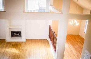
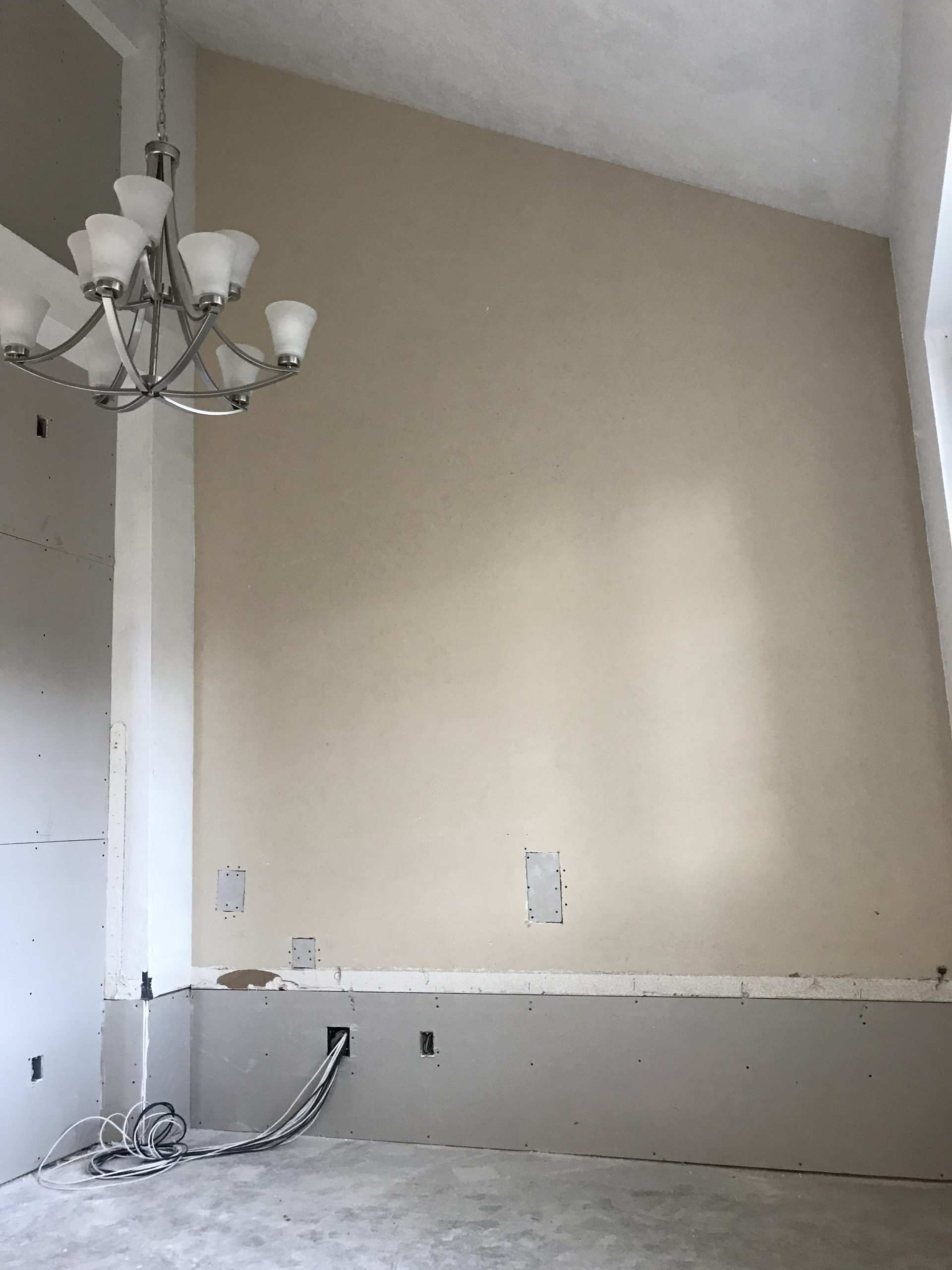
Luckily, I have a very understanding wife that let me take the area just off the living room. This came with a few conditions that we will get into a little later. Needless to say, initially, the area was relatively useless in regard to useable space in the home. again, fortunately, I married into a family that can do anything to a new or existing build (wanna see? Visit Riverwood Building Company’s Site).
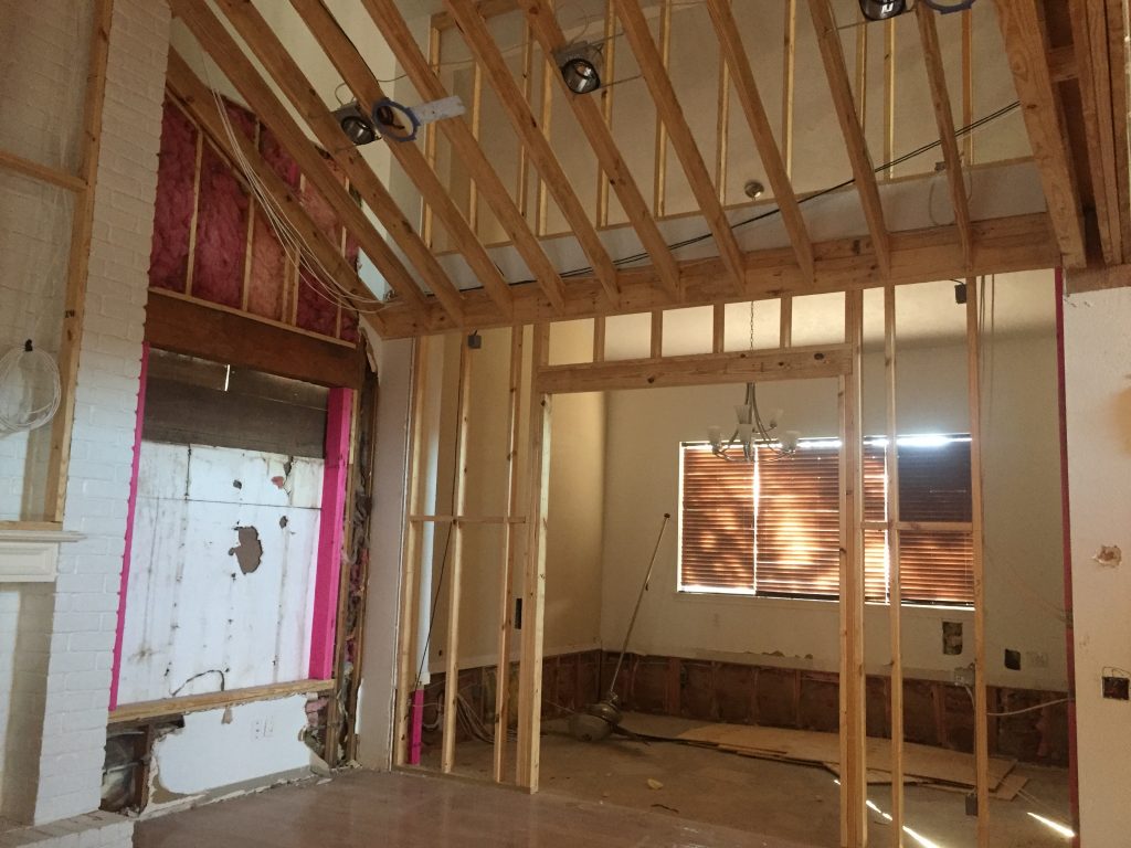
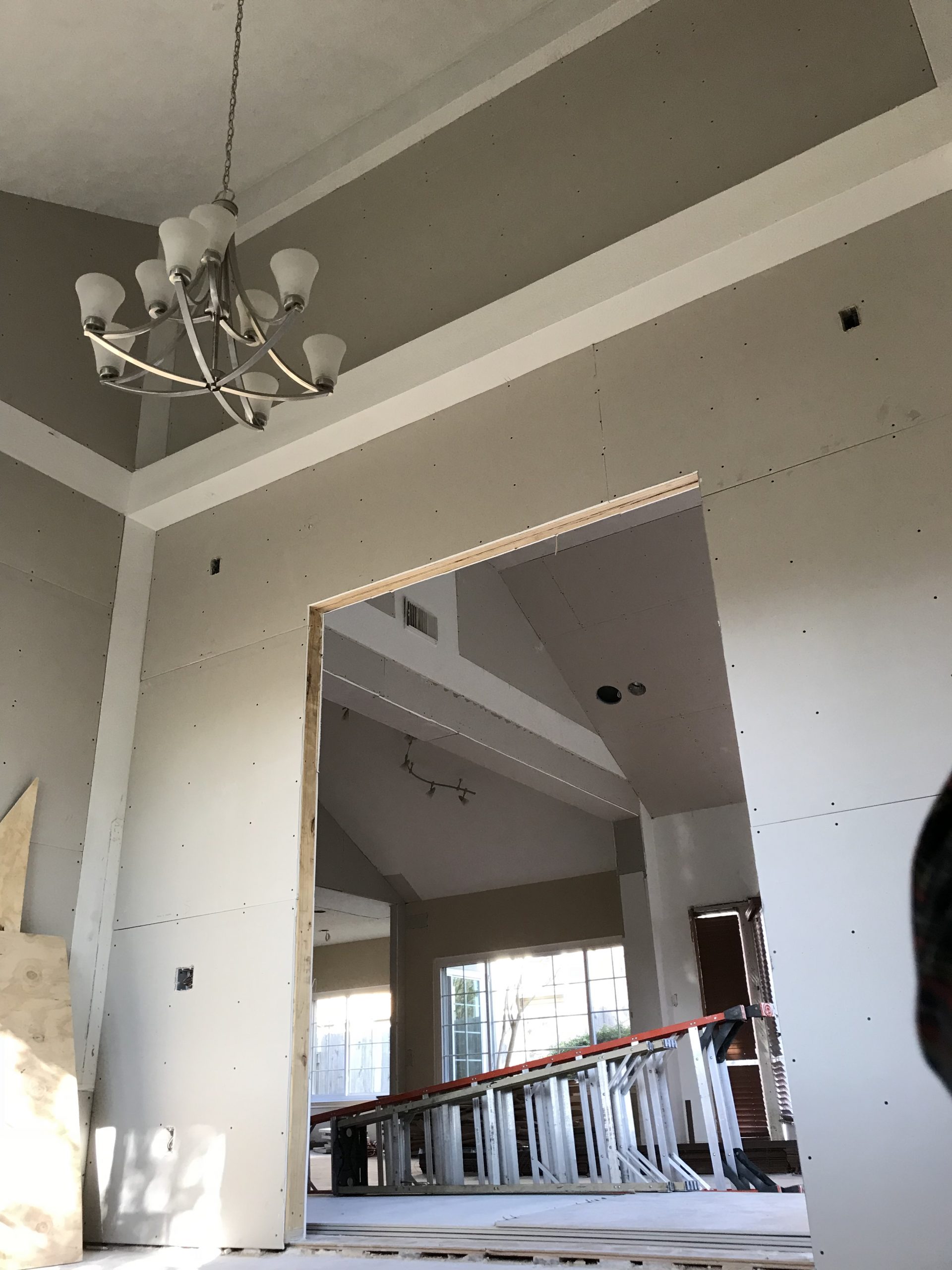
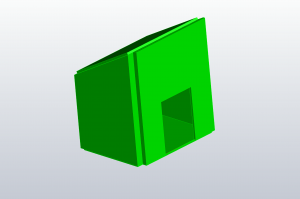
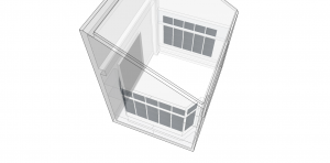
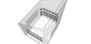
As you can see, the area was elevated, overlooking the living room (thanks 80’s Texas contemporary architecture). I still have yet to have someone explain what the builders were thinking when they added that area. (If anyone can give me an explanation, please email me Bryan@EverythingRecording.com. I’d love to know). After a little bit of planning, we tore out the handrail, dropped the floor to match the lower level, and framed out the area.
Initial Footwork
Determined to learn from my mistakes, I brought Jeff in as soon as possible. While there wasn’t a lot structurally I could do after we framed in the room, there were things I can do organizationally. After all, one of the conditions was that I couldn’t do any more structural alterations. Even though this condition made Jeff’s job a little tougher, I must admit that it served this article and especially you, the reader. Let’s face it, most of us aren’t made of money and do not have the ability to make major changes to a room.
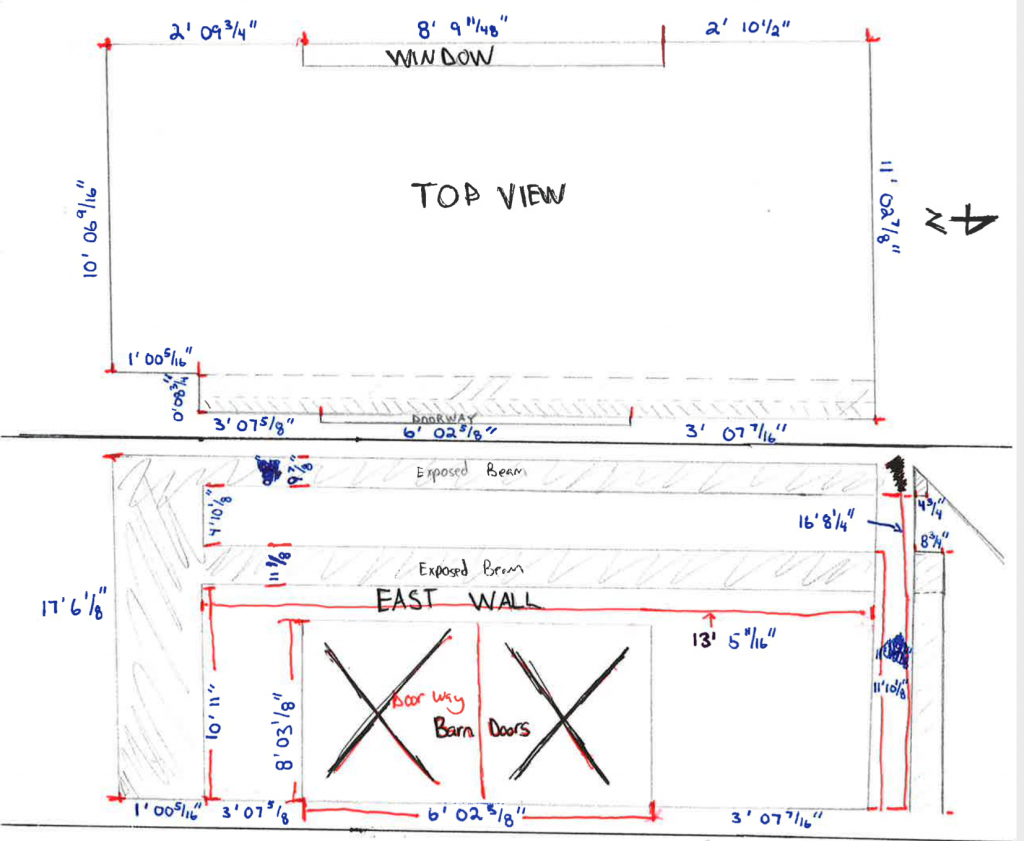
The first step in getting to know the room was measuring out space. Once the drywall was up, I took a lot of pictures of the area from just about every angle I could. Then, I used a laser disto to measure out the entire area. Although Jeff would have been content with the length, width, and height, I had the ability to measure, then draft the area in CAD. While this could be considered overkill on my part, the more data you send, the easier and quicker analysis will be for Jeff.
Under Pressure
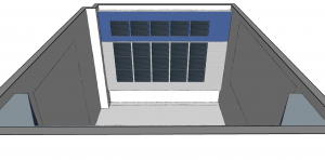
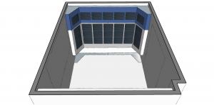
This part is where Jeff took over. With all of the measurements, Jeff performed a sound pressure mapping study. He built a single-faced 3D model of the room and virtually placed a single omni sound source in several positions in the room. The goal of this study is to determine the best mix position based on the frequency response of the room. Essentially, if you start with the area that needs the least intervention, you’ll have the best chance of success in dealing with room issues.
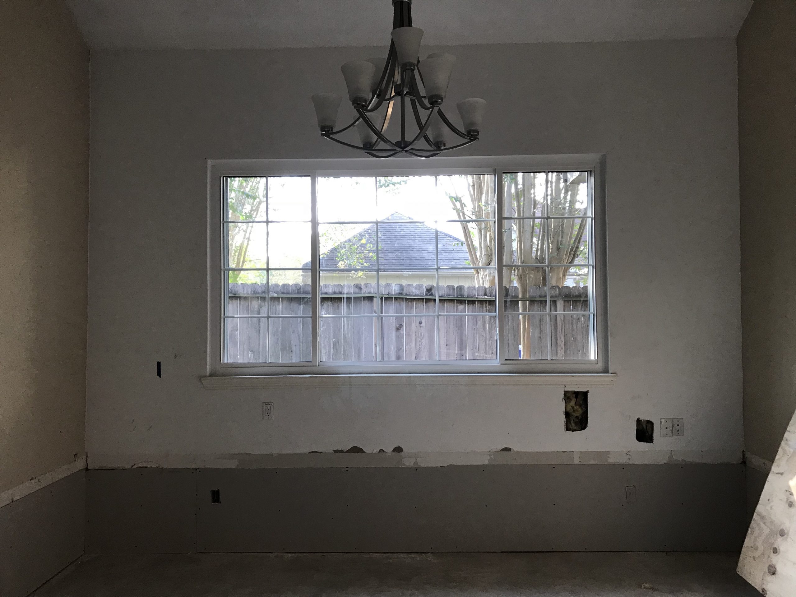
Initially, Jeff looked at the area facing the window as the ideal mix location.
This would be the obvious first choice due to the downward-sloped ceiling over the mix position acting as a built-in “ceiling cloud”. So Jeff began pressure mapping at this location, then moved on to a couple more places to see if the hunch was correct.
Acoustical Forensics
The software he employs specializes in irregular-shaped rooms and determines various room modes (areas where particular frequencies build up and resonate). Acoustical properties are assigned to different surfaces based on their building materials and Jeff can take a deeper look at individual frequencies. The main frequency range Jeff is looking at in the study is from 20Hz to 400Hz). When I pressed why this particular range, Jeff responded with a quote from the great Floyd Toole “Below 400Hz, the room is the dominant feature. Above 400Hz, the speaker is the dominant feature” 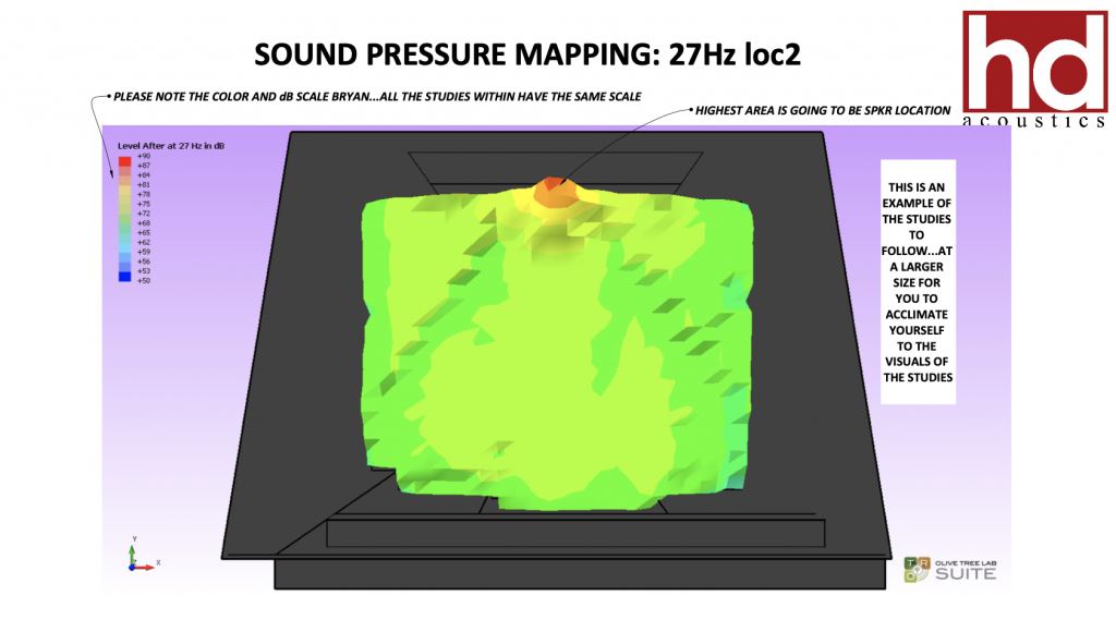
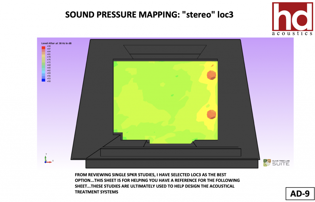
This is an example of the sound pressure mapping study where the simulated speaker location was placed on the west wall. The study is mapping 27Hz.Once Jeff analyzed the single omni source in various positions in the room, he determined that the north wall was the best mix location. To verify this position, a “stereo simulation” placed two speakers in the ideal mix position, and frequency response was measured. REPLACE IMAGE With Stereo speaker at Final Position (same freq)
Sound Judgement
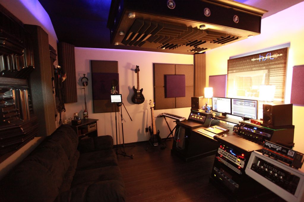
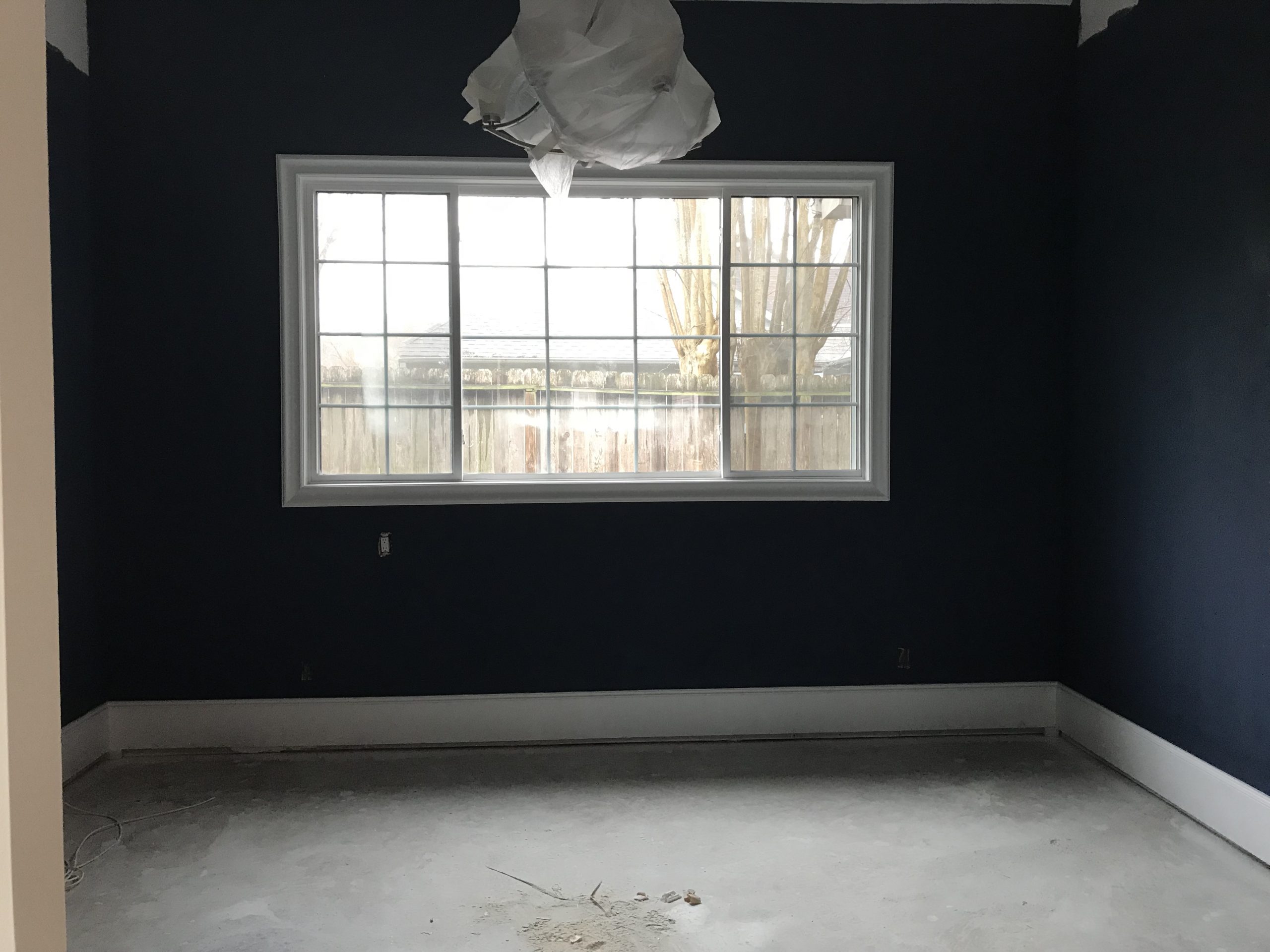
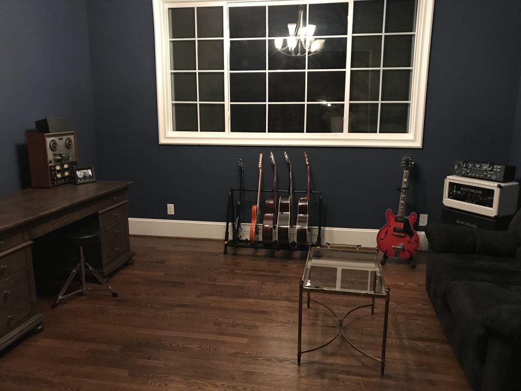
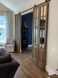
With the mix position determined, I could now get to work organizing the studio. By this time, the room had been painted, the barn doors had been installed, and my wife bought me an incredible five-year anniversary gift – a desk.
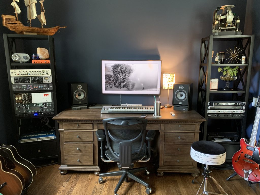
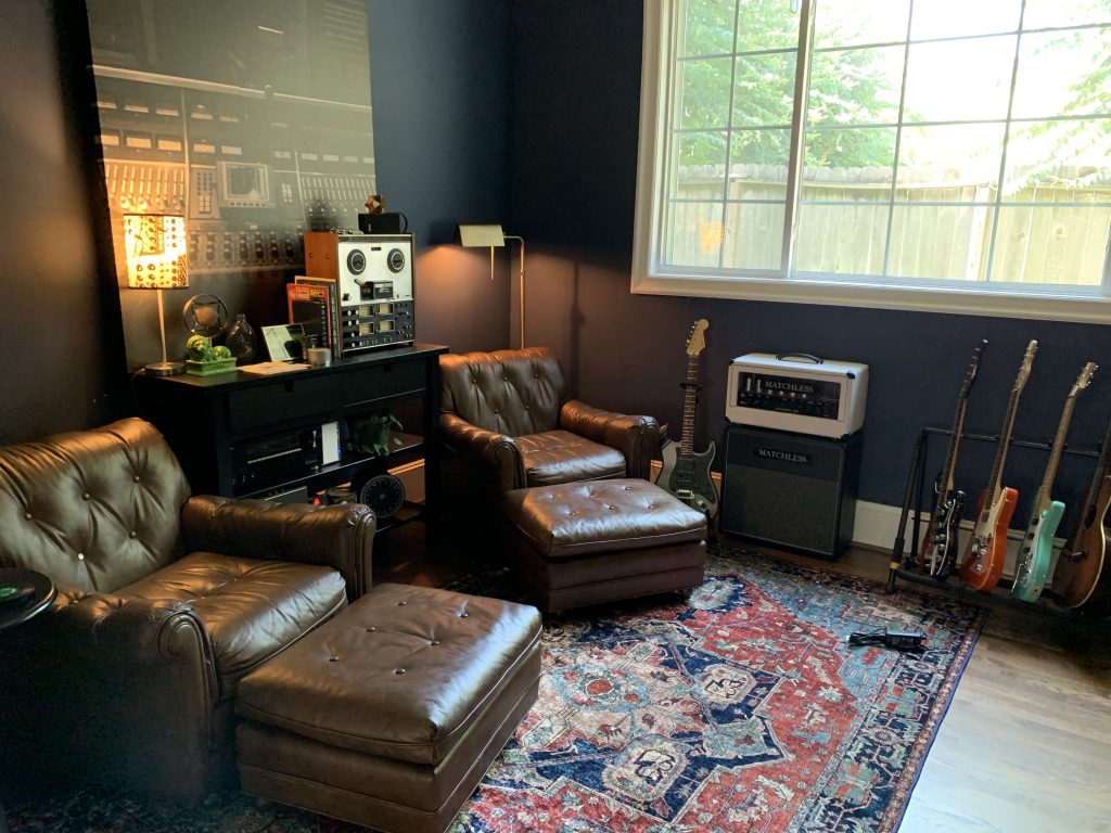
After several iterations of furniture layout, we settled on the setup you see in the pictures above. Now that we had a floorplan, it was Jeff’s turn again to analyze the room, only this time, using real data instead of a model. Using a room measurement mic, we recorded an acoustical sweep at several positions in the room using each individual speaker, as well as both speakers. The purpose of the in-room acoustical testing is two-fold: 1), to verify the initial simulated sound pressure mapping study was accurate, and 2), to use real-world data to determine the treatment plan. The modeled results agreed very close to the actual in-room testing data. Although there were small differences, these could be attributed to slight differences between the acoustical properties of the building materials actually used versus the materials in the model.
Digging In
Taking a deeper look at the actual test data, we can get a better idea of what is happening in the room pre-treatment. First, let’s look at the mix position below. For those new to acoustics, we will use the words “resonance” and “null”. What we mean by “resonance” is a buildup at a particular frequency. The opposite goes for “null”, where a dip in the frequency occurs.
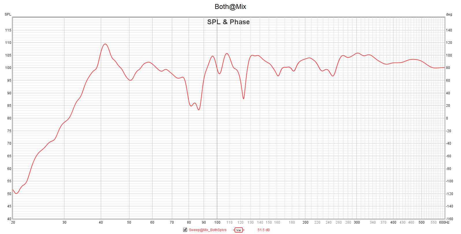
At the mix position, we see a hefty resonance around 42Hz, followed by several nulls at 85Hz and around 120Hz. The end goal with treatment is to see a graph like the one above, but with a more flat response across all frequencies.
In Treatment
Using all of this preliminary data, Jeff began working on a treatment plan. Because this is a case-by-case step in the journey, Jeff initially got a feel for what type of project I wanted to go with. Because I had access to carpenters, we initially went with a plan to create all of the treatment from scratch. The room definitely had some limitations due to the layout so Jeff had to work around quite a bit. Additionally, one of the conditions for the wife giving me this room off the side of the living room was that it had to look less like a studio. This definitely created a “fashion over function” debacle but I must say Jeff handled it with the patience of a saint. Here is the initial plan Jeff came up with.
This design involved quite a bit of construction but took a modular approach. This would satisfy the “no major construction” condition the wife laid out but would use significant custom work building each piece. As you can see, the layout of the room with the large window on one side and the doorway on the other really limited options for the side walls. After a few more discussions, including which would serve this article best, we decided to go with a slightly different plan. While this plan required more work on Jeff’s part, he was very understanding. This is one of the reasons I highly recommend using HD Acoustics. Jeff is very flexible in approach and understands the give and take of treating a home studio.
To Be Continued
I’m sure you’re wondering what exactly this new plan entails but don’t worry, we will cover it in graphic detail in Part 3. See you then!
If you’re as impatient as I am, in the meantime you should check out Jeff’s website at http://www.hdacoustics.net/. He’s got some beautiful designs along with some very big-name studios he’s designed.


